FOR 3D, 2D MODELING, ROUTING CREO PARAMETRIC ZUKEN SOFTWARE INDUSTRIAL SKILLS YOUTUBE CHANNEL LINK AS FOLLOWS PLEASE SUBSCRIBE THE CHANNEL
:https://youtube.com/@CAD_Modeling?si=NfpgQUGXiHh42uNH
https://youtube.com/@CAD_Modeling?si=NfpgQUGXiHh42uNH
What is can bus?
Control Area Network (CAN) bus is a serial communication protocol that allows devices to exchange data. (e.g. sensor data)
It is widely used in vehicles, working like a nervous system
Removed complex dedicated wiring.
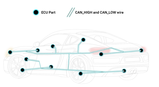
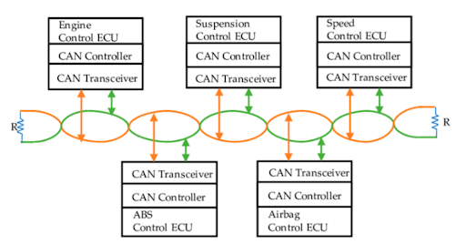
electronic control units' (ECUs) are like parts of the body, interconnected via the CAN bus Information sensed by one part can be shared with another.
what is an ECU?
automotive CAN bus system, ECUs can e.g. be the engine control unit, airbags, audio system
up to 70 ECUs
ECU can prepare and broadcast information (e.g. sensor data) via the CAN bus (consisting of two wires, CAN low and CAN high). The broadcasted data is accepted by all other ECUs on the CAN network - and each ECU can then check the data and decide whether to receive or ignore it.
What is CAN bus physical & data link layer (OSI)?
Can is described by a data link layer and physical layer
ISO 11898-1 describes the data link layer.
ISO 11898-2 describes the physical layer.
CAN is often presented in the 7 layer OSI model.
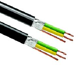
CAN bus physical layer defines things like cable types, electrical signal levels, node requirements, cable impedance.
ISO 11898-2 dictates a number of things, including below:
Baud rate: CAN nodes must be connected via a two wire bus with baud rates up to 1 Mbit/s (Classical CAN) or 5 Mbit/s (CAN FD)
Cable length: Maximal CAN cable lengths should be between 500 meters (125 kbit/s) and 40 meters (1 Mbit/s)
Termination: The CAN bus must be properly terminated using a 120 Ohms CAN bus termination resistor at each end of the bus
What is CAN bus physical & data link layer (OSI)?
benefits of CAN bus
History of CAN bus
Pre CAN: Car ECUs relied on complex point-to-point wiring
1986: Bosch developed the CAN protocol as a solution
1991: Bosch published CAN 2.0 (CAN 2.0A: 11 bit, 2.0B: 29 bit)
1993: CAN is adopted as international standard (ISO 11898)
2003: ISO 11898 becomes a standard series
2012: Bosch released the CAN FD 1.0 (flexible data rate)
2015: The CAN FD protocol is standardized (ISO 11898-1)
2016: The physical CAN layer for data-rates up to 5 Mbit/s standardized in ISO 11898-2
What is a CAN frame?
What is a CAN frame?
SOF: The Start of Frame is a 'dominant 0' to tell the other nodes that a CAN node intends to talk
ID: The ID is the frame identifier - lower values have higher priority
RTR: The Remote Transmission Request indicates whether a node sends data or requests dedicated data from another node
Control: The Control contains the Identifier Extension Bit (IDE) which is a 'dominant 0' for 11-bit. It also contains the 4 bit Data Length Code (DLC) that specifies the length of the data bytes to be transmitted (0 to 8 bytes)
Data: The Data contains the data bytes aka payload, which includes CAN signals that can be extracted and decoded for information
CRC: The Cyclic Redundancy Check is used to ensure data integrity
ACK: The ACK slot indicates if the node has acknowledged and received the data correctly
EOF: The EOF marks the end of the CAN frame
How to log CAN bus data?
To connect your CAN logger to your CAN bus using an adapter cable:
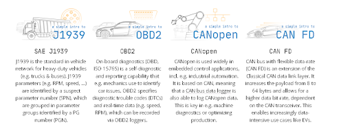
Cars: In most cars, you simply use an OBD2 adapter to connect.
In most cars, this will let you log raw CAN data, as well as perform requests.
Heavy duty vehicles: To log J1939 data from trucks.
CANopen: For CANopen logging, you can often directly use the CiA 303-1 DB9 connector
J1939 protocol for heavy-duty.
Components work together to make communication happen:
Message Sending: When a node needs to send information, it creates a message and puts it on the bus. For example, a sensor might send a message about the temperature to the control unit.
Message Receiving: All nodes connected to the bus receive the message, but only the intended recipient(s) process the information. The identifier in the message helps each node decide if the message is relevant to them.
Error Checking: CAN bus has built-in error checking to ensure that messages are transmitted accurately. If a message is corrupted, it’s ignored and re-sent, ensuring reliable communication.

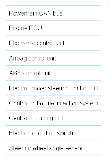
The powertrain CAN bus (fast bus), which allows information to be transmitted at speed of up to 500 kbit/s.
It serves for communication between the control units on the engine and transmission lines and can be in the dominant state when the ignition is on:
Comfort" system CAN bus (slow bus), which allows the transmission of information at speed of up to 100 kbit/s.
It serves for communication between the control units included in the "Comfort" system and others, can be in the dominant state when the ignition of the vehicle is off:
The CAN bus communication model with ECU nodes in the vehicle.









No comments:
Post a Comment